Pump Type Follows:

Monday, December 22, 2008

Typical parts in a centrifugal pump

A centrifugal pump is a relatively simple pump. Design, types and numbers of parts vary depending on centrifugal pump brand, type and configuration.

Typical main pump parts:

Casing/backplate:

  • Contains impeller where fluid is transferred from inlet to outlet.
  • Includes inlet and outlet ports.
  • Typically flexible port orientation.
  • Typically fitted to an adapter

Shaft:

  • Rotates impeller which is fixed to it.
  • Is fixed to the motor and rotates with it.

Impeller:

  • Transfers fluid from inlet to outlet with increased capacity and pressure
  • Is fixed on the shaft and rotates with it.
  • Typical types are open, semi-open or closed.

Shaft seal:

  • Seals between rotating shaft and stationary casing.
  • Typically a mechanical seal, external or internal.
  • Typically available as single, single flushed and double flushed seal.

Adapter:

  • Fixes pump casing to the motor.

Motor:

  • Rotates shaft (impeller) which is fixed to it.
  • Typically a 3-phase electrical motor.
  • Typically available for various electrical site supplies (voltage and frequency).
  • Typically available in various protection classes (flameproof etc.).

Other parts:

  • Seals, motor cover, seal flushing, coupling/base (base-mounted pump).

Typical materials:

  • Steel parts of 316L or 304 stainless steel.
  • Elastomers of NBR, EPDM, FPM, PTFE.

Monday, December 15, 2008

The Principle of a centrifugal pump

The centrifugal pump transfers fluid at a certain capacity from one point to another in a process. The pump builds up fluid pressure to overcome losses in the process. Capacity and pressure are created by the rotating impeller inside the pump casing.


General principle:

·         Fluid enters the pump casing and impeller center and is forced into a circular movement by the impeller vanes and the centrifugal force. The fluid thus leaves the casing with increased pressure and velocity.

·         Typically suitable for low viscous, non-particulate and non-aerated fluids such as beer, CIP, cream, juice, milk, soft drinks, water etc.


Single-stage principle:

The fluid inlet, the built-up of velocity and pressure and the fluid outlet all happens in one stage (one casing and one impeller).


Multi-stage principle:

·         Fluid enters the pump casing and impeller center, and fluid pressure and velocity are built up in the first stage (casing and impeller) similar to the single-stage pump.

·         Fluid with increased pressure and velocity is directed to the second stage (casing and impeller), where the fluid pressure and velocity is further increased.

·         The result is a pressure increase (boost) in each stage, where the total pressure increase depends on the number of stages in the pump.

·         Typically available with 2-4 stages.


Priming of a centrifugal pump:

·         The pump casing should always be filled with fluid before starting the pump to ensure correct operation.

·         The pump can operate with a positive inlet pressure (flooded inlet) or with a negative inlet pressure (suction lift).

·         For suction lift, fluid can remain in the pump casing by using a non-return valve in the suction line.


Monday, December 8, 2008

Basic of Centrifugal Pump

A centrifugal pump is typically the most common sanitary pump type used in sanitary processes. Benefots include a relatively low purchase cost, wide selection, simple design and easy maintenance.

The various aspects of centrifugal pumps are very important to consider when dealing with flow technology and flow equipment. Understanding the aspects of centrifugal pumps makes it easier to select correct pumps, optimize processes and minimize costs.

Process with centrifugal pump (principle)

On the process itself centrifugal pump can arrange in many type, the example of centrifugal pump arrangement on the process system can see on the picture bellow:


Centrifugal Pump Type

Centrifugal pump design can see the parts assembly as follows:


Centrifugal Pump Design


Examples of centrifugal pumps

  1. A centrifugal pump is used in processes with non-viscous and nonparticulate fluids, e.g. beer, CIP, cream, milk, soft drink and purified water.
  2. There are typically many types of centrifugal pumps available for various types of applications.
  3. The main parts of a centrifugal pump are motor, shaft, adapter, shaft seal, impeller, casing and seals.
  4. A centrifugal pump is typically selected from a pump curve or a pump selection program.

Thursday, December 4, 2008

Pump performance curve

The head and flow rate determine the performance of a pump, which is graphically shown in Figure 5 as the performance curve or pump characteristic curve. The figure shows a typical curve of a centrifugal pump where the head gradually decreases with increasing flow.

As the resistance of a system increases, the head will also increase. This in turn causes the flow rate to decrease and will eventually reach zero. A zero flow rate is only acceptable for a short period without causing to the pump to burn out.

Electrical Energy Equipment: Pumps and Pumping Systems


Figure 5. Performance Curve of a Pump

Pump operating point
The rate of flow at a certain head is called the duty point. The pump performance curve is
made up of many duty points. The pump operating point is determined by the intersection of the system curve and the pump curve as shown in Figure 6.


Figure 6. Pump Operating Point (US DOE, 2001)

Pump suction performance (NPSH)
Cavitation or vaporization is the formation of bubbles inside the pump. This may occur when at the fluid’s local static pressure becomes lower than the liquid’s vapor pressure (at the actual temperature). A possible cause is when the fluid accelerates in a control valve or around a pump impeller.

Vaporization itself does not cause any damage. However, when the velocity is decreased and pressure increased, the vapor will evaporate and collapse.

This has three undesirable effects:
  • Erosion of vane surfaces, especially when pumping water-based liquids
  • Increase of noise and vibration, resulting in shorter seal and bearing life
  • Partially choking of the impeller passages, which reduces the pump performance and can lead to loss of total head in extreme cases.

The Net Positive Suction Head Available (NPSHA) indicates how much the pump suction exceeds the liquid vapor pressure, and is a characteristic of the system design. The NPSH Required (NPSHR) is the pump suction needed to avoid cavitation, and is a characteristic of the pump design.

Tuesday, December 2, 2008

Pumping System Characteristics

Resistance of the system:
Head Pressure is needed to pump the liquid through the system at a certain rate. This pressure has to be high enough to overcome the resistance of the system, which is also called “head”. The total head is the sum of static head and friction head:

1. Static head

Static head is the difference in height between the source and destination of the pumped
liquid (see Figure 2a). Static head is independent of flow (see Figure 2b). The static head at a certain pressure depends on the weight of the liquid and can be calculated with this equation:

Head (in feet) = (Pressure (psi) X 2.31)/Specific gravity

Static head consists of:
  • Static suction head (hS): resulting from lifting the liquid relative to the pump center line. The hS is positive if the liquid level is above pump centerline, and negative if the liquid level is below pump centerline (also called “suction lift)
  • Static discharge head (hd): the vertical distance between the pump centerline and the surface of the liquid in the destination tank.

2. Friction head (hf)

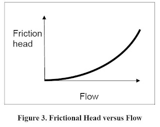
This is the loss needed to overcome that is caused by the resistance to flow in the pipe and fittings. It is dependent on size, condition and type of pipe, number and type of pipe fittings, flow rate, and nature of the liquid. The friction head is proportional to the square of the flow rate as shown in figure 3. A closed loop circulating system only exhibits friction head (i.e. not static head).

Electrical Energy Equipment: Pumps and Pumping Systems

In most cases the total head of a system is a combination of static head and friction head as shown in Figures 4a and 4b.

Monday, December 1, 2008

Pumping Systems

Pumping systems account for nearly 20% of the world’s electrical energy demand and range from 25-50% of the energy usage in certain industrial plant operations (US DOE, 2004).

Pumps have two main purposes:
  • Transfer of liquid from one place to another place (e.g. water from an underground aquifer into a water storage tank)
  • Circulate liquid around a system (e.g. cooling water or lubricants through machines and equipment)

The main components of a pumping system are:

  • Pumps (different types of pumps are explained in previous section)
  • Prime movers: electric motors, diesel engines or air system
  • Piping, used to carry the fluid
  • Valves, used to control the flow in the system
  • Other fittings, controls and instrumentation
  • End-use equipment, which have different requirements (e.g. pressure, flow) and therefore determine the pumping system components and configuration.

Examples include heat exchangers, tanks and hydraulic machines. Electrical Energy Equipment: Pumps and Pumping Systems.

The pump and the prime mover are typically the most energy inefficient components.